Finite Element Modeling of Piezoceramic Disks
including Radiation into a Fluid Medium
Jan Kocbach1, Per Lunde2 and Magne Vestrheim1
1University of Bergen, Department of Physics, Allégt. 55, N-5007 Bergen, Norway
2Christian Michelsen Research AS, P.O. Box 6301, N-5892 Bergen, Norway
Introduction
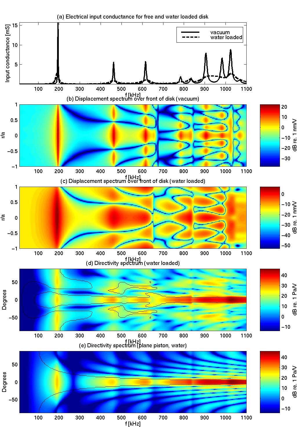
Finite element (FE) modeling is a valuable tool for transducer construction, and may be both time- and cost-saving in practical design. This has been the longterm motivation for the development of a FE program for axisymmetric piezoelectric transducer structures including radiation into a fluid medium at UoB and CMR. Results for piezoceramic disks [1,2,3] and for piezoceramic disks with a front layer of varying thickness [4,5], where the effect of fluid loading has been neglected, have been presented in previous works. In the present work, the effect of the surrounding fluid medium is included in the FE formulation, using fluid finite elements and infinite wave envelope elements of variable order [6,7]. Using this FE formulation, the effect of fluid loading on a piezoceramic disk has been investigated, and the vibration on the front face of the piezoceramic disk has been compared to the resulting radiated sound pressure field, and to the corresponding sound pressure field radiated from a plane piston with the same radius.Method
The FE formulation used for the analysis of axisymmetric piezoelectric transducer structures vibrating in vacuum has been described in detail in Ref. kocbach1999a. In the present paper, focus is set on the modeling of the sound pressure field radiated from the piezoceramic transducer structure into an infinite fluid medium. Consider a piezoelectric disk radiating into a fluid of infinite extent, as shown in Fig. 1(a). It is of interest to be able to calculate the near and far field sound pressure field radiated from the piezoelectric disk, the directivity pattern and the source sensitivity response for a large frequency band. The methods used for the modeling of the infinite fluid medium which are most often found in the literature, may be divided into two main categories:- 1.
- The fluid medium is modeled using the Boundary Element (BE) method (see e.g. Refs. kirkup1998,schenck1967,amini1992,balabaev1996), where fluid boundary elements are coupled directly to the piezoelectric finite elements used for the modeling of the piezoelectric disk. When the BE method is used, it is only necessary to discretize the boundary of the piezoelectric disk.
- 2.
- Part of the fluid medium adjacent to the piezoelectric disk [the volume V1 in Fig. 1(a)] is modeled using fluid finite elements, and some mechanism is applied at the artificial boundary S1 to minimize the reflections from the artificial boundary. This mechanism may either be various types of dampers [12] (e.g. plane wave dampers), which absorb certain parts of the outgoing sound field, matching to analytical solutions [13], non-reflecting boundary conditions (e.g. the Dirichlet-to-Neumann global condition [14]), or infinite elements [6,7,15,16]. When the infinite element approach is used, the entire infinite fluid region outside the artificial boundary S1 is modeled using elements of infinite extent, where the infinite domain is mapped onto a finite domain using special mapping functions.